Home » Without Label » Schematic Diagram For Opel Ignition With A 7 Pin Module / Ignition Module Bosch 0 227 100 008 Wiring Rennlist Porsche Discussion Forums / It shows the components of the circuit as simplified shapes, and the gift and signal associates between the devices.
Schematic Diagram For Opel Ignition With A 7 Pin Module / Ignition Module Bosch 0 227 100 008 Wiring Rennlist Porsche Discussion Forums / It shows the components of the circuit as simplified shapes, and the gift and signal associates between the devices.
Schematic Diagram For Opel Ignition With A 7 Pin Module / Ignition Module Bosch 0 227 100 008 Wiring Rennlist Porsche Discussion Forums / It shows the components of the circuit as simplified shapes, and the gift and signal associates between the devices.. When autocomplete results are available use up and down arrows to review and enter to select. Brown std opel 4 pin module. In 1862, a german entrepreneur adam opel founded an industrial company that got his name, which initially occupied a niche for the production of sewing machines. A longer pulse width means a more delayed, 'retarded' spark, while a shorter pulse width means an earlier 'advanced' spark. I don't have a wiring diagram for the car, which makes it diffecult for me to try and trace the were to look for opel corsa model the coil module?.
If not, the structure won't function as it ought to be. Posted by anonymous on oct 16, 2014. Pin 4 green live feed (battery +) pin 5 brown not connected. Clicking this will make more experts see the question and we will remind you when it gets answered. Assortment of mercruiser ignition wiring diagram.
Opel Vauxhall Vectrab Z16xe 1 6 16v Ignition Coil Diagnostic Functionality Test Youtube from i.ytimg.com This is a wiring diagram for the factory ignition module. Connector e9 is waterproof connector, and the pin numbers are based on you looking at the open end of the connector (not the back where the wires enter it). A longer pulse width means a more delayed, 'retarded' spark, while a shorter pulse width means an earlier 'advanced' spark. The shift switch shown in the wiring diagram is used on alpha models only. If not, the structure won't function as it ought to be. Where dust or grease can be a problem, provide covers for the module and the gas control to limit contamination. I don't know, but i think msd, accel, and others are the same. On the discovery there is a purpose made plug behind the panel on the drivers side rear, behind the rear lamp.
When autocomplete results are available use up and down arrows to review and enter to select.
A longer pulse width means a more delayed, 'retarded' spark, while a shorter pulse width means an earlier 'advanced' spark. There are two different sized terminals on the module, so make sure you check the wiring diagram below before putting the spade terminals on. Touch device users, explore by touch or with swipe gestures. Dust or grease accumulation heavy accumulations of dust or grease can cause controls to malfunction. Lt1 power module wiring diagram and insructions thank you for purchasing our product. Cant seem to find wiring diagrams anywhere, basically i need to know the wire colors and data on the coil pack. Each component ought to be set and connected with different parts in specific way. The timing of the trailing edge determines the amount of advance: I've got an opel kadett e 1990/91 16sv engine (pierburg 2e3 carb) the ignition module is the siemens ez plus 5wk6 221 (gm part no 90 340 026) and it's mounted prominently on the firewall/bulkhead. Charging system voltage, measured at the coil's + terminal, must never exceed 13.9 volts, at any rpm level. Assortment of mercruiser ignition wiring diagram. This electronic ignition system operates with full 12 volts. Placement of the module varies from model to model so check the appropiate service manual of your vehicle for the.
Clicking this will make more experts see the question and we will remind you when it gets answered. (delphi with barcode ka) the side of this ecm has a f02d. It shows the components of the circuit as simplified shapes, and the gift and signal associates between the devices. The engine should be the a14xer but seems autodata lists it as z14xep. Brown std opel 4 pin module.
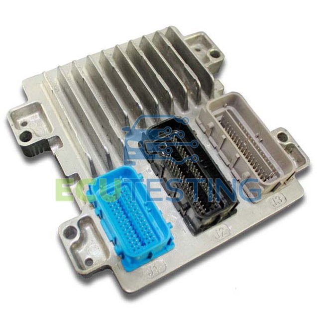
Corsa E And Adam Ecu Failure from www.ecutesting.com The timing of the trailing edge determines the amount of advance: Placement of the module varies from model to model so check the appropiate service manual of your vehicle for the. Pin 2 blue, supplementary feed (ignition) pin 3 white, earth. Idle air bypass iab diagram. Charging system voltage, measured at the coil's + terminal, must never exceed 13.9 volts, at any rpm level. There are two different sized terminals on the module, so make sure you check the wiring diagram below before putting the spade terminals on. A nema 4 enclosure is recommended for the ignition module. General motors 7 pin hei ignition control remote mount module team camaro tech gm 4 electronic wiring diagram free back to stock holley trigger using points dist antiquated distributor on a small block 5 diode fix technical duraspark ii problem conversion replace with 8 rebuilding ignitions ford or mopar.
Dust or grease accumulation heavy accumulations of dust or grease can cause controls to malfunction.
Diagram together with gm hei ignition module wiring diagram. The 7 pin hei module. Pin 6 red supplementary feed (ignition) pin 7 black earth. This is a wiring diagram for the factory ignition module. A longer pulse width means a more delayed, 'retarded' spark, while a shorter pulse width means an earlier 'advanced' spark. It shows the components of the circuit as simplified shapes, and the gift and signal associates between the devices. A wiring diagram usually gives opinion virtually the relative aim and concord of devices and. Bbq grill battery ignition module from back side to show 2 wires to attach to so the electrodes can bolt inside the grill and spark next to the. Posted by anonymous on oct 16, 2014. Where dust or grease can be a problem, provide covers for the module and the gas control to limit contamination. If not, the structure won't function as it ought to be. Touch device users, explore by touch or with swipe gestures. If you have an ignition harness with five wires, just don't connect the dark green wire that would go to pin 3.
It is recommended only for ordinary lawn & garden equipment. Clicking this will make more experts see the question and we will remind you when it gets answered. The diagram below shows the pinouts of the bim024 module as well as the corresponding wire colours for the module above. Bbq grill battery ignition module from back side to show 2 wires to attach to so the electrodes can bolt inside the grill and spark next to the. Brown std opel 4 pin module.
Coil Induction Wiring Diagrams Youtube from i.ytimg.com Diagram together with gm hei ignition module wiring diagram. I don't have a wiring diagram for the car, which makes it diffecult for me to try and trace the were to look for opel corsa model the coil module?. Posted by anonymous on oct 16, 2014. I need a wiring diagram for a 7 pin trailer board plug. It is recommended only for ordinary lawn & garden equipment. Assortment of mercruiser ignition wiring diagram. The engine should be the a14xer but seems autodata lists it as z14xep. I don't know, but i think msd, accel, and others are the same.
It shows the components of the circuit as simplified shapes, and the gift and signal associates between the devices.
If you have an ignition harness with five wires, just don't connect the dark green wire that would go to pin 3. Brown std opel 4 pin module. Assortment of mercruiser ignition wiring diagram. Please verify pin locations in these diagrams carefully and if they are incorrect email me at pmcmahon@nethere.net ability to use a digital meter is a must. Diagram together with gm hei ignition module wiring diagram. Advance control signal is a white wire pin e goes to ampseal pin #12; When autocomplete results are available use up and down arrows to review and enter to select. The engine should be the a14xer but seems autodata lists it as z14xep. Click on the image to enlarge, and then save it to your computer by right clicking on the image. This is a wiring diagram for the factory ignition module. Pin 6 red supplementary feed (ignition) pin 7 black earth. This wiring diagram is for the 1980 and later four pin ignition module. The illustrations in the diagnostic manual are printer friendly.